Applied Fluids mechanics
We are one of the leading manufacturer and supplier of a wide array of Applied Fluid Mechanics Lab Equipments.
These products are used in various industrial field and Laboratory. Moreover, we have a set of advanced machinery and technology assisted by experienced professionals involved in manufacturing highly efficient and durable products.
1. Wind Tunnel
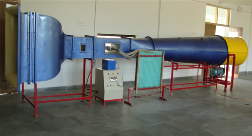
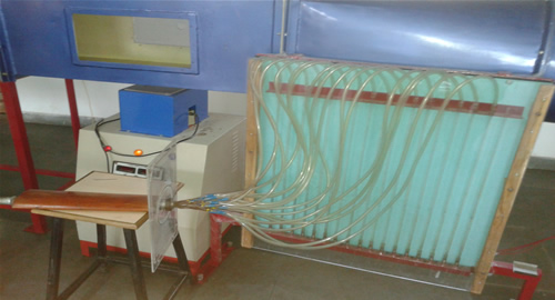
Wind tunnel is one of the most important facilitate for experimental work in aerodynamics and fluid flow. Its purpose is to provide a region of controlled air flow into which models can be inserted. This region is termed as the WORKING SECTION. Wind tunnel is closed working section with bell mouth entry. The tunnel is of simplest tube section open type along which air is propelled. The propulsion is usually provided by a fan downstream of the working section.
Length |
6 meter |
Air Channel Area |
400mm X 400mm |
Air Velocity |
0 to 25 m/s |
Height |
1.5 meter |
Motor |
2 HP |
Horn Section Area |
1m X 1m |
2. Hydraulic Tilting Flume
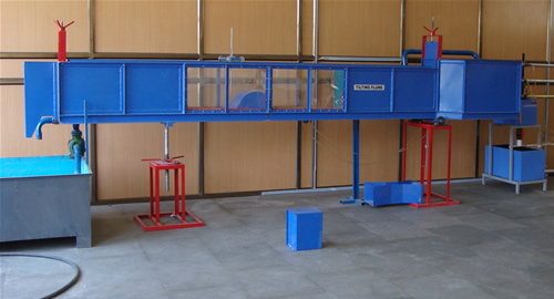
The flume consists of a channel type. At the inlet, a flow steadying section is provided so that there will be less disturbance at the test section. The gates provided at the upstream and downstream of the test section help to regulate the depth of flow. Depth measurements can be achieved with the help of a hook or point gauge mounted on a trolley which gives longitudinal and transverse movement. The slope of the bed can be adjusted, manually or electrically, to give positive or negative slopes. An arrangement to obtain quiescent flow. Gates for regulating the depth of flow, one at the upstream and the other at the downstream A point gauge trolley for depth measurement. Tilting bed. Models of Sharp crested, Broad crested and Ogee weir, Venturi flume, and Spillway.( Optional At an Extra Cost) Transparent middle half test section for visualisation of flow over test section a€“ 4 to 6 mtrs.s
RANGE OF EXPERIMENTS
- Study of Open Channel flow with slope.
- Study of Specific Energy Curve.
- Study of Hydraulic Jump.
- Study of Nappe Profiles over a Sharp Crested Weir. Optional if models are provided.
- Calibration of Sharp Crested, Broad Crested and Ogee Weir. Optional if models are provided Calibration of a Venturi Flume. Optional if models are provided.
Length |
6 meter |
Open Channel Area |
300mm X 400mm |
Height |
1.5 meter |
Motor |
1-2 HP |
Tank Area |
1m X 1m |
3. Losses In Pipes Apparatus
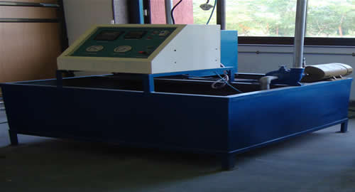
In hydraulic engineering practice, it is frequently necessary to estimate the head loss incurred by a fluid as it flows along a pipeline. For example, it may be desired to predict the rate of flow along a proposed pipe connecting two reservoirs at different levels. Or it may be necessary to calculate what additional head would be required to double the rate of flow along an existing pipeline.
Loss of head is incurred by fluid mixing which occurs at fittings such as bends or valves, and by frictional resistance at the pipe wall. Where there are numerous fittings and the pipe is short, the major part of the head loss will be due to the local mixing near the fittings. For a long pipeline, on the other hand, skin friction at the pipe wall will predominate. In the experiment described below, we investigate the frictional resistance to flow along a long straight pipe with smooth walls.
When fluid through equipment, friction takes places. The calculation of friction with considerable accuracy & missing it, whenever excessive, are important engineering problems. The knowledge of the mechanism of friction & laws applicable to the flow of fluids is useful.
Length |
2 meter |
Height |
1.5 meter |
Motor |
1 HP |
Tank Area |
1m X 1m |
Pipes |
3 Nos. |
4. Water Hammer
Water hammer (or, more generally, fluid hammer) is a pressure surge or wave resulting when a fluid (usually a liquid but sometimes also a gas) in motion is forced to stop or change direction suddenly (momentum change). Water hammer commonly occurs when a valve is closed suddenly at an end of a pipeline system, and a pressure wave propagates in the pipe. It may also be known as hydraulic shock.
This pressure wave can cause major problems, from noise and vibration to pipe collapse. It is possible to reduce the effects of the water hammer pulses with accumulators and other features.
If the pipe is suddenly closed at the outlet (downstream), the mass of water before the closure is still moving forward with some velocity, building up a high pressure and shock waves. In domestic plumbing this is experienced as a loud banging resembling a hammering noise.
Length |
7 meter |
Height |
4 meter |
Tank |
700mm X 700mm X 1m |
5. Centrifugal Pump Test Rig
Pumps have come to occupy an important place in a large number of industries which have different requirements. Attempt to meet the needs of industries has resulted in the design and development of various types of pumps. To match a pump for a particular application and to use a pump effectively, it is necessary to know the pump characteristics. In this experiment, students are exposed to the method of determination of pump characteristics, which is similar for all types of pumps. The experiment is conducted using a parallel-series centrifugal pump test rig.
To match a pump for a particular application and to use a pump effectively, it is necessary to know the pump characteristics. In this experiment, students are exposed to the method of determination of pump characteristics, which is similar for all types of pumps. The experiment is conducted using a parallel-series centrifugal pump test rig.
6. Turbine Test Rig
We are offering Francis Turbine Test Rig of world class quality and fabrication to our clients. Finding extensive application in the industries, these rigs are employed for the testing purposes. The flow measuring system in these test rigs comes with orifice meter and pressure gauges. Additionally, we also provide the facility for tachometers and heavy duty polymer trolley wheels in these test rigs.
Switch and DOL starter suitable for the above motor pump set, mounted on a panel board Piping system consisting of pipes, valves, fittings complete with suitable for the test rig Fiber glass line M.S. sump size 1550 x 950 x 500 mm(Approximate) height to store sufficient water for independent circulation through the unit for experimentation and arranged with in the floor space of the main unit.
Diamond Packege Download
NOTES:- Also Provide AFM Lab Equipment based on your Requirement.


